0 引 言
近年来,煤炭开采逐渐向深部发展,应力增高趋势明显,动压影响下巷道变形更加严重,维护难度增加。深部高应力动压巷道的围岩控制是保证煤矿安全生产的主要任务之一,也是煤炭深部开采工程的重点与难点。近距离高瓦斯煤层开采时,常采用在邻近层中掘预抽巷的方法解决瓦斯超限的问题。预抽巷需承受多次采动影响,尤其是在高应力环境下,此类巷道的围岩变形剧烈,维护困难[1]。国内外对于深部近距离煤层开采下部动压巷道支护的研究为本论文研究提供了有益借鉴,如:部分学者运用弹塑性力学对近距离煤层群开采时巷道围岩应力分布及破坏特征进行研究,总结分析覆岩活动规律,提出合理巷道支护理念;有学者分析近距离煤层开采时复杂的空区形态分布,提出锚杆+锚索+注浆的联合支护技术;文献[2-3]提出近距离煤层开采过程中动压巷道关键部位耦合支护等理论;围岩强度强化理论是锚杆对巷道围岩在开掘之后的松散范围进行锚固从而改善岩石峰后力学参数[4-6]。上述不同的支护理论与方法在现场实践中均取得了很好效果,但对于近距离煤层群动压巷道围岩立体支护研究较少,相关实践成果有待于进一步丰富[7-10]。
以平顶山矿区某矿己15-31010运输巷为研究对象,针对高应力多次采动影响下巷道围岩控制的难题,通过模拟分析巷道围岩在动压影响下的应力分布及围岩变形特征,掌握巷道围岩塑性区变形规律,提出相应的围岩控制对策,设计支护方案并进行现场工业性试验,并对支护方案实际效果进行检测,以期为类似条件工程提供借鉴参考。
1 工程概况
某矿三水平开采己组煤,上下煤层分别为己14、己15煤层,属近距离煤层群开采,采用在己14煤层中掘预抽巷的方法解决己15煤层工作面瓦斯超限的问题。己15-31010工作面地表最高标高为+430 m,工作面标高为-705~-775 m,埋深1 015~1 130 m,己14、己15煤层埋深较大。己14煤层在己15煤层上方12~14 m处,己15-31010工作面为内错布置,水平错距47 m。己15-31010运输巷在己14煤层回采工作面下方,为梯形巷道,宽4.4 m,低帮高2.4 m,高帮高3.6 m。巷道布置如图1所示。
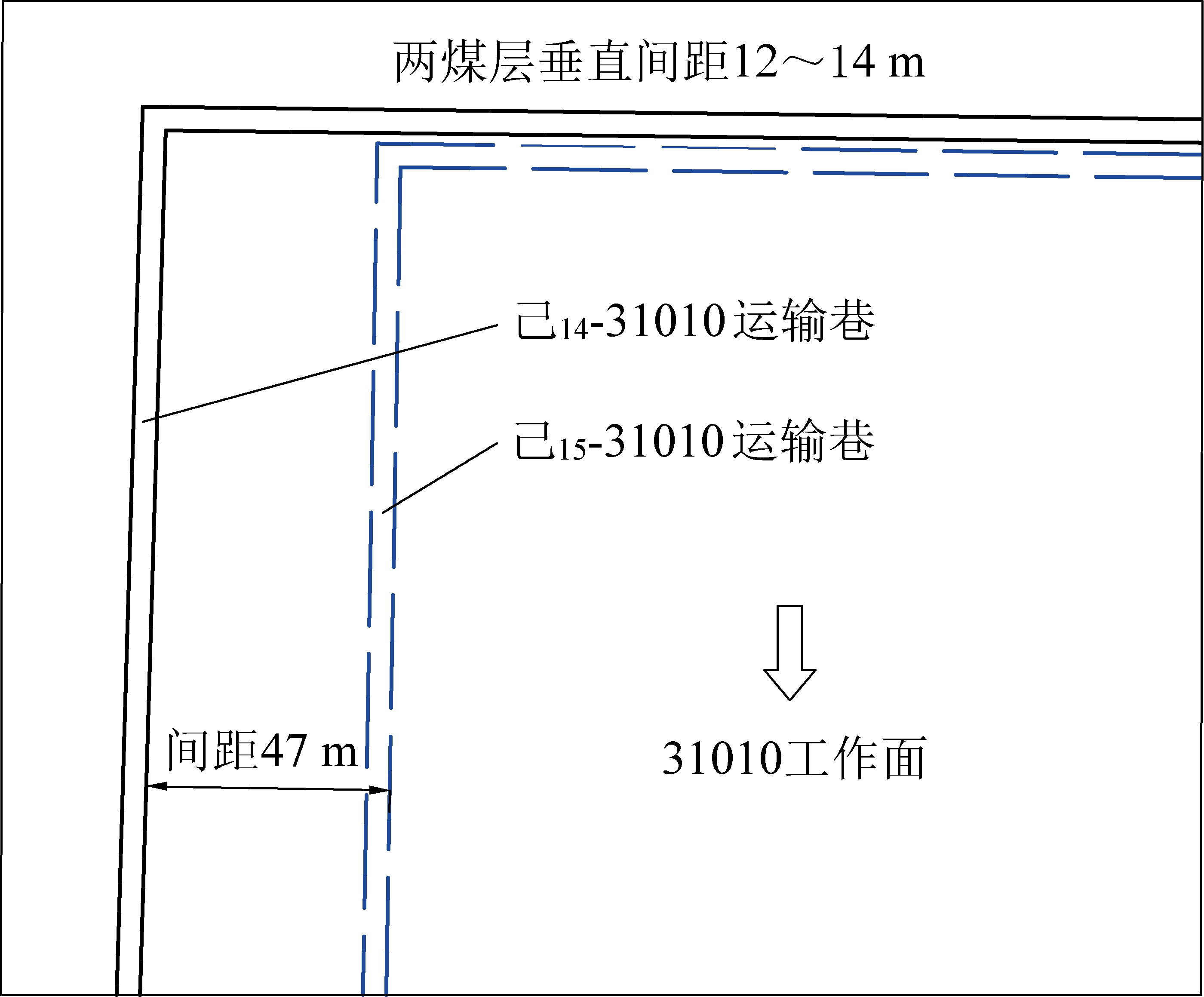
图1 巷道布置
Fig.1 Indication of roadway layout
2 巷道围岩变形机理
根据该矿三水平地应力观测结果,最大、最小主应力倾角接近水平,中间主应力接近垂直,应力场为水平构造应力场。为深入分析己15煤层开采过程中己15-31010运输巷的围岩应力变化特征,建立包含己14和己15煤层及回采巷道的三维计算模型,对巷道围岩应力分布及表面位移进行系统分析。模型尺寸400 m×400 m×200 m,测点布置在己15-31010运输巷中点位置,测点布置在该巷道两帮及顶底板中。
2.1 巷道围岩垂直应力变化及变形分析
对己14煤层回采过程中巷道围岩应力分布及表面位移进行分析。监测点围岩垂直应力变化如图2所示,横坐标负值部分表示工作面未推进至测点位置。
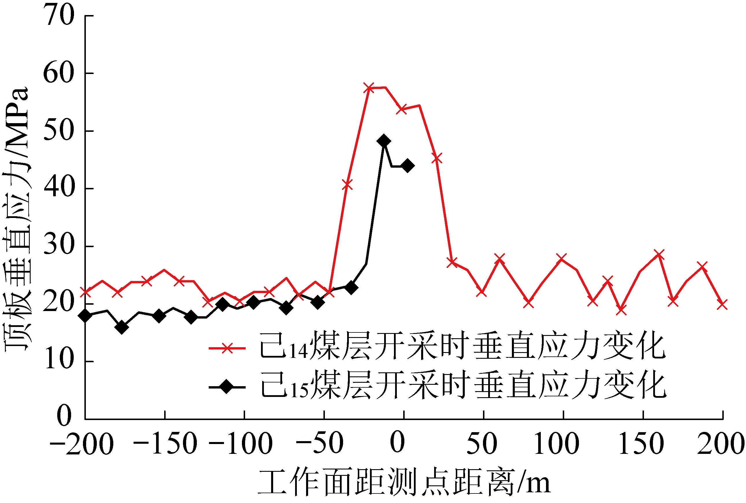
图2 己15-31010运输巷垂直应力变化
Fig.2 Vertical stress change of Ji15-31010 machine roadway
由图2可知,己15-31010运输巷在上煤层开采过程中,距采面60 m范围内受到支承压力的影响,产生应力升高区,其中40 m范围内为支承压力显著影响区;采面推过后己15-31010运输巷处于卸压区,围岩应力急剧下降。当采面推过40 m后,动压影响不显著。己14煤层完成后,上部采空区垮落岩体处于逐渐压实过程,所以在未受二次采动影响前,围岩垂直应力呈现上升趋势。己15-31010运输巷距己15-31010工作面30 m时,受到超前支承压力影响。与首次采动影响时相比,二次采动支承压力峰值降低18.72%。己15-31010运输巷收敛变形如图3所示。

图3 己15-31010运输巷收敛变形
Fig.3 Convergence deformation of Ji15-31010 machine roadway
由图3可知,己15-31010运输巷在距上煤层采面40 m时开始发生收敛变形,巷道顶底及两帮收敛变形持续增大,当采面推过40 m时,收敛变形基本稳定。己14采面开采之后,己15-31010运输巷位于上煤层采空区下,下煤层工作面回采时,己15-31010运输巷受到二次采动影响。己15-31010运输巷在己14采面开采之后未受二次采动之前,巷道表面发生位移,但变化量不大,距离己15-31010工作面30 m时,巷道表面位移变化速率增加。
2.2 己15-31010运输巷围岩塑性区变化
己15-31010运输巷围岩经历了巷道开挖、上层保护层开采以及己15-31010工作面开采的应力重新分布,围岩塑性区变化如图4所示。
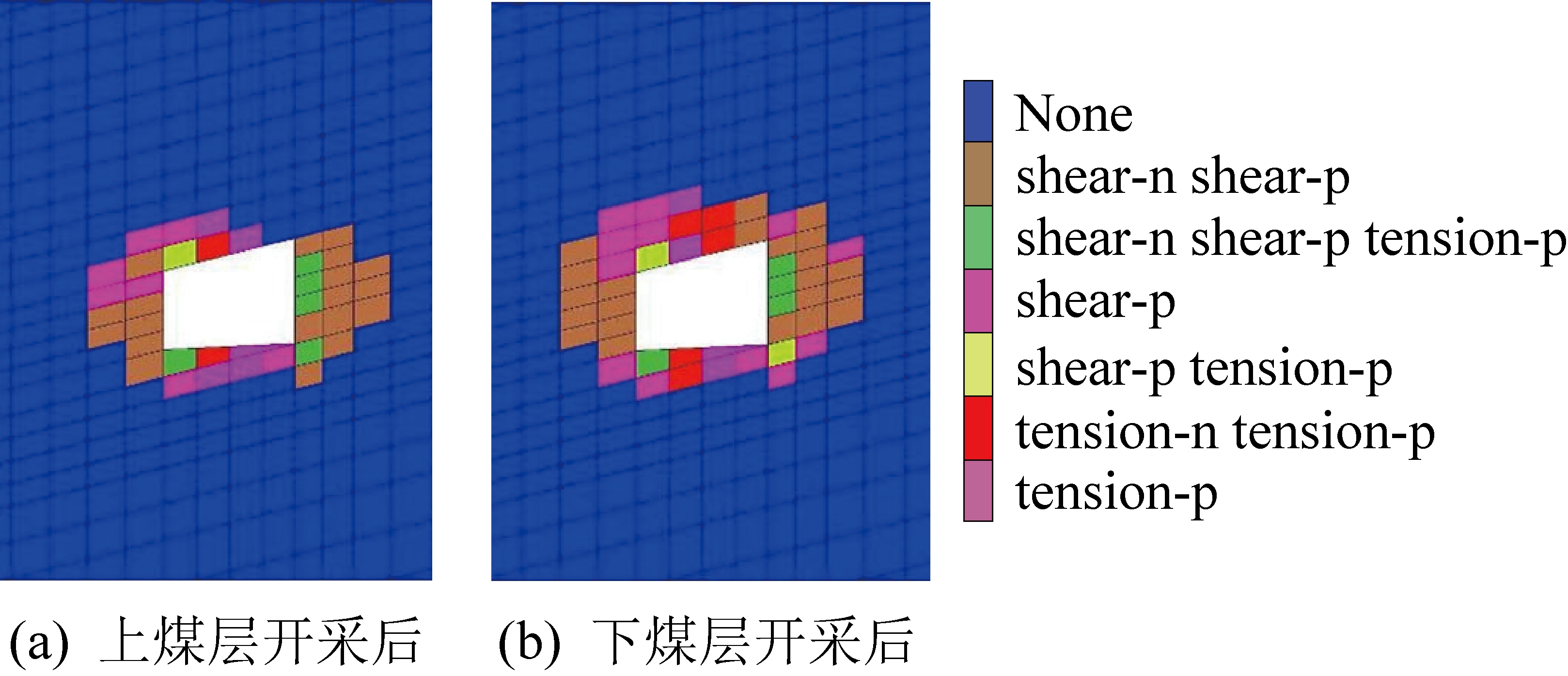
图4 己15-31010运输巷围岩塑性区变化
Fig.4 Plastic zone change of surrounding rock of Ji15-31010 wad entry
己15-31010运输巷顶板为岩层,两帮为煤层,顶板出现以水平应力为主的剪应力,巷道顶板中水平应力不能传到靠近邻空岩面的直接顶板附近,难以形成挤压作用,下部岩石受重力影响形成弯曲[7-8]。当顶底板岩层应力超过岩石抗拉强度时,顶底板发生破坏。由图4可知,上煤层开采后,巷道围岩塑性区发生显著变化,两帮塑性区范围最大为3 m,顶板塑性区最大为1.5 m。下煤层工作面开采后,巷道围岩受二次采动应力影响,塑性区进一步增大,两帮塑性区范围增加不明显,顶板塑性区范围增大至2.5 m。
两帮的塑性区范围明显大于顶底板,两帮煤体强度相对较小,容易片帮,煤体对顶板的支护作用逐渐降低,导致顶板支护难度加大。
3 围岩控制对策与支护方案
3.1 围岩控制对策
针对该矿己15-31010运输巷受重复采动影响剧烈的特点,结合数值分析,提出以“卸-让-抗”为核心的动态立体支护对策。
1)局部围岩卸压,转移集中应力。在应力集中区或关键部位适时进行钻孔卸压,释放围岩变形能,减小初次支护形成结构所受的围岩压力,将围岩局部集中应力转移到围岩深部,达到卸压效果[11-14]。掘进期间采用钻孔等方式对掘进工作面前方及两帮进行大范围卸压,降低围岩高应力保护围岩强度,降低支护难度和突出倾向性,保证高应力巷道在采动影响下的围岩稳定。对己15-31010运输巷支护过程中卸压方案进行模拟分析,卸压前后帮部围岩应力分布如图5所示。
由图5可知,在卸压前,围岩集中荷载位于距巷道表面2.5 m处,卸压后,帮部集中荷载转移至8.0 m处,将此集中荷载转移至围岩深部,使支护范围内水平应力降低,减小支护结构破坏。
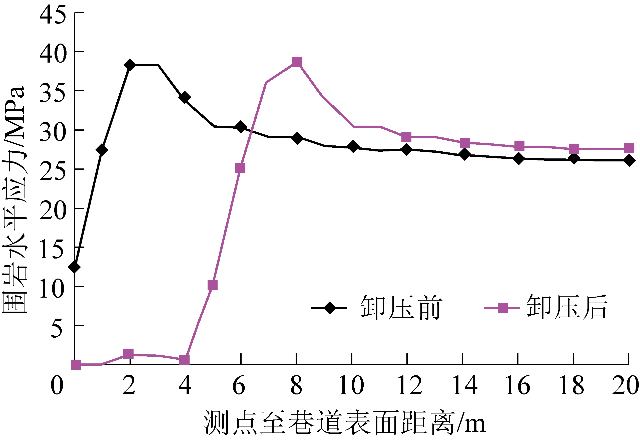
图5 卸压前后帮部围岩水平应力分布
Fig.5 Horizontal stress distribution of surrounding rock before and after pressure relief
2)采用让压支护结构,缓解初期过大载荷。采用高强让压锚杆和大直径高延伸率三维锚索沿巷道横向和纵向对围岩深部与浅部进行耦合支护。让压锚杆能释放围岩初期变形压力,缓解支护结构承受的过大荷载。
3)“锚梁网+三维锚索”联合支护,提升围岩承载能力,控制围岩变形。“锚梁网”支护适用于围岩变形量较大的动压巷道,在压力显现明显和围岩比较破碎的复杂条件下,有利于改善围岩锚固层的应力状态[15-16],提高锚杆支护的承载能力,防止顶板破坏,提升次生组合拱的承载能力,有效控制围岩持续变形。
“三维锚索”支护可在煤岩表面形成径向、切向、轴向三个方向的预应力[17-18],是能在巷道顶板的水平及垂直方向同时提供挤压应力的主动支护方式,增强煤岩的整体抗压强度,缩短围岩达到平衡状态的时间,提高巷道煤岩的整体稳定性和承载能力[19]。“三维锚索”支护立体示意如图6所示。
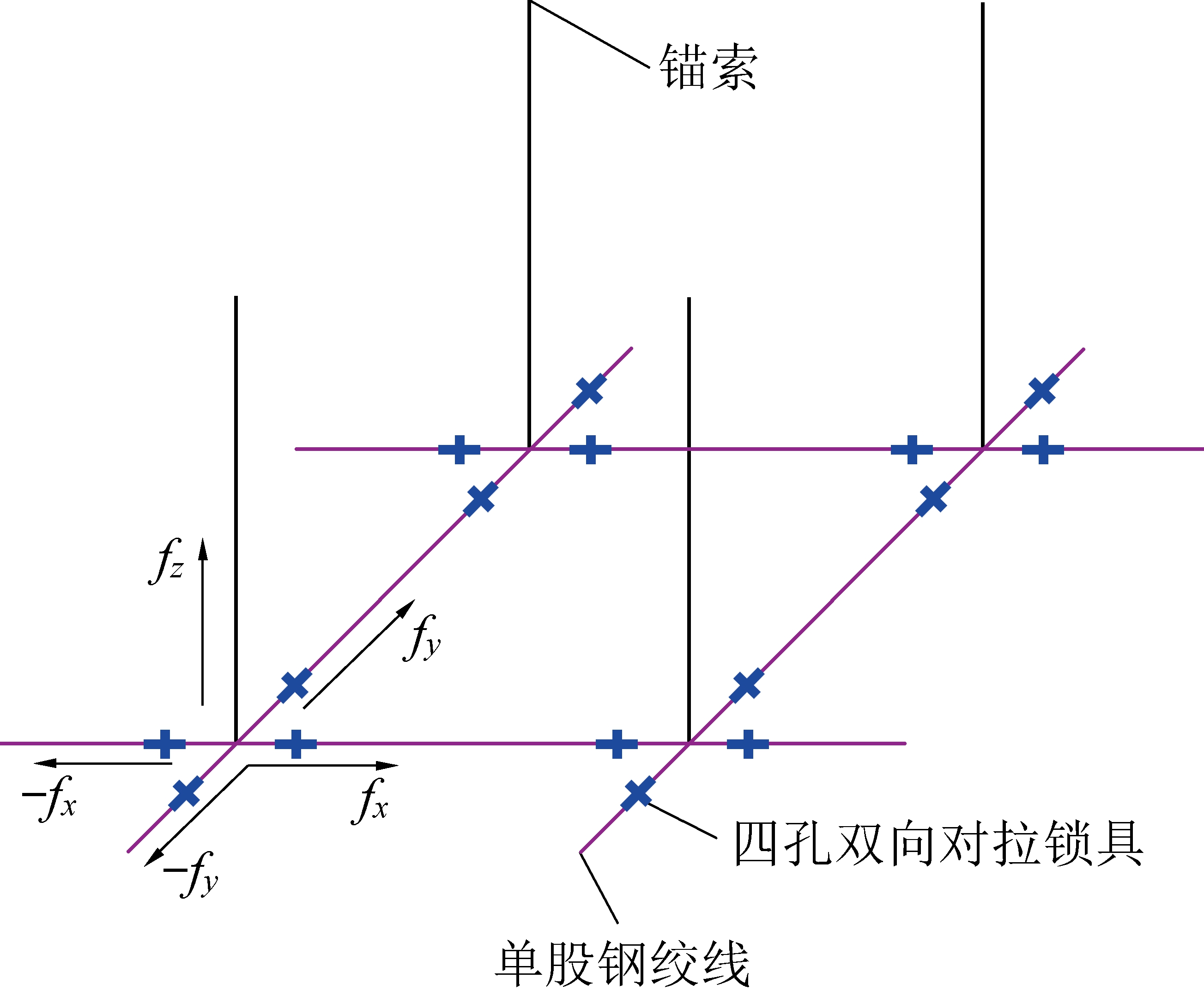
fx—切向预应力;fy—径向预应力;fz—轴向预应力
图6 “三维锚索”立体示意
Fig.6 “Three-dimensional anchor cable”signature
顶板三维锚索采用高强度预应力钢绞线,每根锚索在锚孔外形成十字状单股钢绞线,与相邻的锚杆与锚索采用四孔双向对拉锁具锁紧。
总之,高应力动压巷道围岩控制一方面要采用降压措施释放部分高应力,以降低支护难度,另一方面采用高强让压锚杆和三维锚索桁架对巷道围岩浅部和深部、横向和纵向进行全方位立体支护,使锚固范围内的围岩处于均一的三向应力状态,有效维护围岩强度,确保巷道围岩稳定。
3.2 巷道围岩支护方案
依据巷道围岩控制对策,提出己15-31010运输巷顶板采用超高强让压锚杆+钢筋网+M型钢带+锚索、帮部采用等强树脂锚杆+钢筋网+钢筋梯梁+锚索的联合支护,并在应力集中区或关键部位进行钻孔卸压的支护方案。超高强让压锚杆参数为ø20 mm×2 400 mm,采用ø20 mm×50 mm让压管,锚杆排距700 mm;钢筋网180 mm×4 000 mm,直径为4 mm。顶板三维锚索规格ø17.8 mm×5 500 mm,两帮锚索规格为ø17.8 mm×3 900 mm,锚索排距1 400 mm。支护方案如图7所示。利用己15运输巷高位瓦斯抽排巷向运输巷施工穿层钻孔,进行控制爆破,对煤体进行超前松动卸压,从而使原始煤体的能量提前释放,同时,在已经施工的巷道两帮施工卸压孔,间距0.7 m,卸压孔规格ø89 mm×12 m。

图7 支护方案示意
Fig.7 Schematic support scheme
4 工程实践
己15-31010运输巷按照设计方案实施后,巷道收敛变形如图8所示。
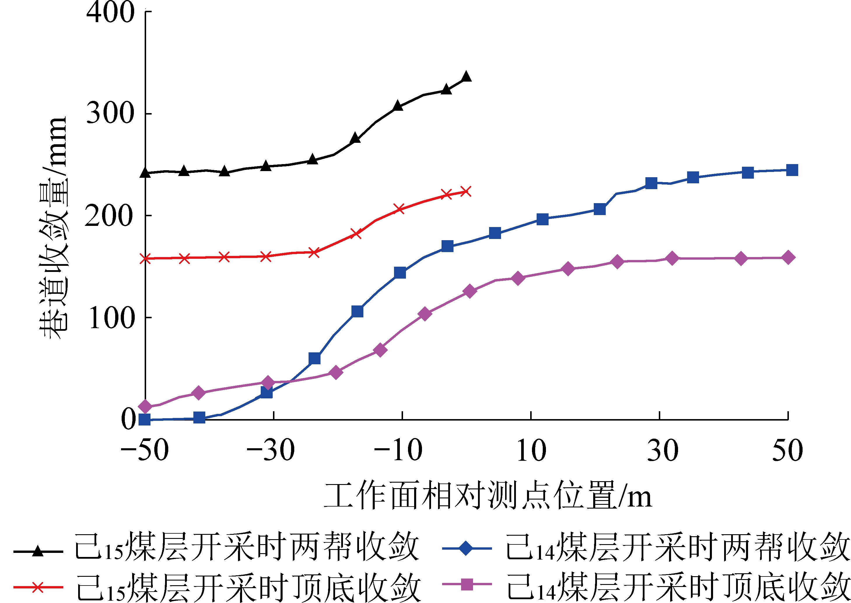
图8 己15-31010运输巷实际收敛变形
Fig.8 Actual convergence deformationof Ji15-31010 machine roadway
由图8可知,根据工业性试验观测结果,上煤层开采过程中,己15-31010运输巷两帮收敛最大为240 mm,顶底收敛最大为156 mm。下煤层回采过程中,两帮收敛最大值为335 mm,顶底收敛最大值230 mm。巷道顶板采用超高强让压锚杆+钢筋网+M型钢带+锚索、帮部采用等强树脂锚杆+钢筋网+钢筋梯梁+锚索的联合支护,并在应力集中区或关键部位进行钻孔卸压的支护技术,有效地维护了巷道的稳定性,取得了预期的效果,巷道支护效果如图9所示。

图9 巷道支护效果
Fig.9 Support effect of roadway
5 结 论
1)数值模拟分析结果表明,己15-31010运输巷围岩表面位移及应力分布受采动影响显著。己14煤层开采过程中,工作面距测点30 m时,巷道围岩垂直应力达到峰值;工作面推过后,两帮塑性区范围最大为3 m,顶板塑性区最大为1.5 m。己15煤层开采时,工作面距测点30 m开始,巷道围岩受采动影响剧烈,工作面推过后,两帮塑性区范围增加不明显。卸压方案有效地将巷道围岩集中应力从距巷道表面2.5 m转移到8.0 m的围岩深部。
2)提出以“卸-让-抗”为核心的巷道动态立体支护对策,设计巷道顶板采用超高强让压锚杆+钢筋网+M型钢带+锚索、帮部采用等强树脂锚杆+钢筋网+钢筋梯梁+锚索的联合支护方案,并在局部高应力区域进行卸压,对设计方案进行工业性试验。
3)现场试验结果表明,采用“卸-让-抗”试验方案后,己15-31010运输巷两帮最大变形量为335 mm,顶底顶底最大变形量230 mm,有效解决了巷道围岩变形严重的问题。
[1] 袁 越,王卫军,袁 超,等.深部矿井动压回采巷道围岩大变形破坏机理[J].煤炭学报,2016,41(12):2940-2950.
YUAN Yue,WANG Weijun,YUAN Chao,et al. Large deformation failure mechanism of surrounding rock for gateroad under dynamic pressure in deep coal mine[J].Journal of China Coal Society,2016,41(12):2940-2950.
[2] ABDUL-WAHED M K,HEIB M Al,SENFAUTE G.Mining-induced seismicity:seismic measurement using multiplet approach and numerical modeling[J].International Journal of Coal Geology,2005,66(1):137-147.
[3] 张 炜,张东升,陈建本,等.极近距离煤层回采巷道合理位置确定[J].中国矿业大学学报,2012,41(2):182-188.
ZHANG Wei,ZHANG Dongsheng,CHEN Jianben,et al. Determining the optimum gateway location for extremelyclose coal seams[J].Journal of China University of Mining & Technology,2012,41(2):182-188.
[4] 祁和刚.深部高应力巷道综合卸压技术研究与实践[J].采矿与安全工程学报,2016,33(6):1023-1029.
QI Hegang.Research and practice on integrated pressure releasing technology in deep coal mine rock roadway under high stress[J].Journal of Mining and Safety Engineering ,2016,33(6):1023-1029.
[5] BECK D A,BRADY B H G.Evaluation and application of controlling parameters for seismic events in hard-rock mines[J].International Journal of Rock Mechanics and Mining Sciences,2002,39(5):633-642.
[6] 崔 魏,陈 威,崔 峰.深部高应力巷道底鼓大变形控制技术研究[J].煤炭工程,2013,45(11):37-39.
[7] 肖忠党,程士宜.深部煤层底板软岩巷道支护方案研究及应用[J].煤炭科学技术,2017,45(S1):43-45.
XIAO Zhongdang, CHENG Shiyi.Reserch and application of soft rock floor roadway in deep coal seam support scheme[J].Coal Science and Technology,2017,45(11):37-39.
[8] 王卫军,袁 超,余伟健,等.深部大变形巷道围岩稳定性控制方法研究[J].煤炭学报,2016,41(12):2921-2931.
WANG Weijun,YUAN Chao,YU Weijian,et al.Stability control method of surrounding rock in deep roadway with large deformation[J].Journal of China Coal Society,2016,41(12):2921-2931.
[9] 李中伟,张 剑,王 挺,等.深部松软煤层动压巷道变形机理与支护技术研究[J].煤炭科学技术,2015,43(11):16-21.
LI Zhongwei, ZHANGJian, WANG Ting,et al.Study on deformation mechanism and support technology of dynamic pressurizer gateway in deep soft seam[J].Coal Science and Technology,2015,43(11):16-21.
[10] 汪占领.深部动压软岩巷道底鼓控制技术研究[J].煤炭工程,2017,49(7):55-57.
Wang Zhanling.Research on floor heave control technology for deep roadway with dynamic pressure soft rock[J].Coal Engineering,2017,49(7):55-57.
[11] IVANOVICA,NEILSON R D,RODGER A A.Influence of prestress on the dynamic response of ground anchorages[J].Journal of Geotechnical and Geoenvironmental Engineering,2002,128(3):237-249.
[12] 陈新年,王景春.矩形巷道围岩应力分布规律模拟试验研究[J].煤炭技术,2017,36(9):12-15.
[13] 王 涛.深部矩形巷道围岩瞬间卸荷动态响应数值模拟[D].邯郸:河北工程大学,2017.
[14] BEARDM D,LOWE M J S.Non-destructive testing of rock bolts using guided ultrasonic waves[J].International Journal of Rock Mechanics and Mining Sciences,2003,40(4):527-536.
[15] 张随喜,张东升,王旭锋,等.曹村矿近距离煤层群下位煤层巷道布置分析[J].煤炭工程,2012(1):46-48.
[16] 张志康,王连国,单仁亮,等.深部动压巷道高阻让压支护技术研究[J].采矿与安全工程学报,2012,29(1):33-37.
ZHANG Zhikang, WANG Lianguo, SHAN Renliang et al.Support Technology of high resistant and yielding property for deep roadway under dynamic pressure[J].Journal of Mining and Safety Engineering, 2012, 29(1), 33-37.
[17] 毕业武,蒲文龙.深部高应力巷道大变形机理与控制对策[J].辽宁工程技术大学学报(自然科学版),2014,33(10):1321-1325.
Bi Yewu, PU Wenlong.Large deformation mechanism and control count ermeasure research of deep high stress roadway[J].Journal of Liaoning Technical University(Natural Science), 2014,33(10):1321-1325.
[18] SEMBLAT J F,LOKMANE N,DRIAD-LEBEAU L.Local amplification of deep mining induced vibrations part.2:simulation of ground motion in a coal basin[J].Soil Dynamics and Earthquake Engineering,2010,30(10):947-957.
[19] 刘 迅,王卫军,吴 海,等.矩形巷道围岩塑性区扩展规律分析[J].矿业工程研究,2017,32(1):14-18.
